


I was looking through my photo reel the other day - to work out if October 2025 had been as warm as October 2026 has been so far. And found a photo of my repaired Honda exhaust stud. Which made me think… that was a year ago??? And also… oh yeah, I never did finish my blog post about my first Helicoil experience. And actually it was 99% finished to be honest. So time to sort out the missing 1% - here’s a finished post:
b0rked
The exhaust on my Honda Helix has been broken for a long time. The previous owner had fitted a “cool” aftermarket exhaust that came all the way from Japan - which seems like a fairly extreme thing to do… until you realise that the list price for the standard factory exhaust (if you can find one at all) is £500… which makes importing one from Japan look like the almost sensible option!

Shortly after buying the bike, I managed to lose the exhaust manifold studs… they vibrated loose and disappeared.
Not knowing any better, I ordered what I thought was the right thing from eBay… and was able to reconnect the exhaust again.
One challenge with that aftermarket exhaust, is that it sits nicely in front of the oil filter bolt… which means cleaning the oil filter (which you’re supposed to do at each oil change - and those are every 1000 miles) means removing the aftermarket exhaust to get proper access to the bolt head. (There’s just about room to spin a spanner, but to have a fighting chance of getting the thing off, means using a socket - which means, exhaust off…)
Ultimately my ham-fisted removal and refitting of the aftermarket exhaust over time (and the fact I’d potentially bought the wrong exhaust studs on eBay) meant that the threads in one of the stud holes were basically destroyed.
I was able to install the exhaust using the one healthy stud… which is less than ideal, but… works, and means I could pass an MOT annd use the bike for buzzing around London… but the reality was, I knew I had to fix it - which meant using a Helicoil.
Helicoil?
A helicoil (if you’re not familiar with them) is a coil of stainless steel wire used to repair stripped and damaged threads. And, done properly - should be stronger than the original threads.
Repairing threads with a Helicoil is a three step process
- Drilling out the remaining thread with the right sized drill bit
- Cutting a new thread with the special tool that comes with the helicoil
- Winding the coil into the hole, and then removing a metal tang - that’ll lock the coil into place
paranoia
The problem with this (for me), is the drilling and cutting… it’s not like you get a second go if you do things wrong.
I think about the early computer programming manuals I’d read as a kid, that said “you can type whatever you want into the computer - and press any button, you can’t break anything” (and yes this is the 8 bit era when there was no storage attached… no rm -rf / to worry about here…)
As such, whilst I knew that I needed to do this… I’ve been dragging my heels, really for months.
You also need special sized drill bits, that you’re unlikely to find in your standard set of bits. For example the exhaust stud on the Helix is an M8 - requiring an 8.3mm drill bit. Ordering a set of those became another excellent excuse for procrastinating.
I also watched this video A LOT:
Because Ari made it look easy… but Ari knows what he’s doing!
I’d also seen this video… where it was all power tools all the time..
As I’d never done this before, I also wanted to find some scrap metal to test on - to get a feel for how this was done. But finding suitable metal just becomes another excuse to procrastinate, until finally - in October 2025 I snapped, and just decided…

Because really - the threads were destroyed, and I really REALLY couldn’t make things any worse.
And - the exhaust had already been removed, for an oil change anyway… and I’d left it off, to MAKE me finally attempt a thread repair, as I knew if I refitted the exhaust, that’d become enough of an excuse (because I know what I’m like…)
Let’s go.
Drilling out the hole went ok… but goodness, the new hole looks so much bigger than the old one…
The challenge was actually the tapping of the hole. I don’t have a tap handle (the kind of thing that you’d have in a tap and die set) but the helicoil kit I have expects you to use one. I started trying to wind the tap in by hand, but couldn’t put enough torque in to actually cut any threads.
There’s also not a lot of room to work, as the exhaust manifold is tucked up by the rear wheel of the Helix.
In the end, I took inspiration from that second YouTube video… I wound the tap tool into a drill… but set the drill to the slowest speed/highest torque I then tried to replicate Ari’s technique from the first video… slowly winding the tap in, then backing it out again - and adding WD40 as some make-do cutting fluid.
The drill allowed me to keep the cutting tool straight, and had plenty of power to cut clear threads ready for the helicoil.
Now time to wind the coil in. You wind it in, until it’s a couple of turns below the surface of the repaired thread. Which - was pretty much all the space I had anyway. A big challenge was removing the locking tang. I’m not able to knock the tang through the hole.
I had to use a screwdriver (again, as seen in the Revzilla video) to remove the tang - as the special tool in the box wouldn’t work.
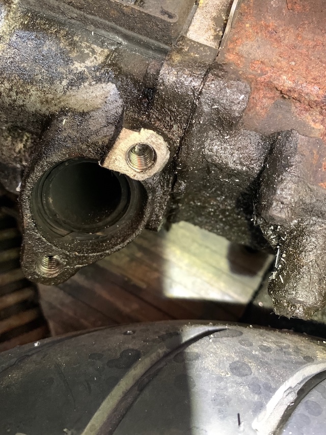
It was at this point I noticed that the other thread had already been repaired at some point in the last 35 years… as now I know what I’m looking at - and that looks like a helicoil to me…
But - we’re done? And very smart it looks too. (My fresh helicoil is at the top of the image - but the lower exhaust stud hole looks like it’s been helicoiled to at some point in the bike’s past…)
Now - the moment of truth…
Repaired threads means I can fit proper Honda studs (thanks David Silver Honda spares) - and it means I can fit a factory OEM exhaust, from my spares bike.
What a transformation! The bike is quieter (although there’s a slight exhaust blow from the manifold to cylinder head joint, because I couldn’t find my new gasket… curses!) - and it also pulls significantly better in the midrange. The aftermarket exhaust had a bit of a flat spot… that just isn’t there with the OEM exhaust.

The challenge is - will the helicoil stay in place the next time I remove the manifold? And annoyingly I’m going to need to remove the manifold at some point, as I couldn’t find the manifold gasket that I KNEW previous me had bought… and was keen to get the bike back together anyway…
…and Sod’s Law, just a few days later, whilst looking for something else, I found my gasket in the boot of the Helix… sigh…
I still need to do a top speed run - but to be honest I’m really happy with how things have turned out. I mean, I’m still scared of the drilling and tapping required to helicoil, but now that I’ve done it once, I feel a lot happier about what’s required to fit one.
Next up, I need to get brave enough to try polishing the scratches out of the speedometer plastics using wet and dry sandpaper. Perhaps that’s my next post about the Helix.
Until then, I should get on with enjoying my newly working super scooter!
coda…
The above was all written last year. As I tidy up the post today - I have to admit the Helix has been working really well on the standard exhaust this year. I’ve managed almost exactly 1000 miles since last October - as the bike is just about due another oil change. 1000 miles in a year is underwhelming - especially as I’ve tried to use it more this year - with regular runs into the city to hang out at the Barbican to work on job applications. Let’s see if I can manage a bit more than that this year. Especially as I have an actual commute these days…